|
Radio Room S.S. Marsodak 1940 |
| The pictures on this page show the radio installation on the S.S. Marsodak circa 1940. The Marsodak was a freighter built in 1919 in Newark, NJ. She was 324 feet long, carried a crew of 27, and did service carrying lumber and wood products along the west coast of the US. The pictures show the setup before and after an upgrade to newer equipment. These pictures were scanned from very small prints, so the quality is not all that one would desire. |
|
|
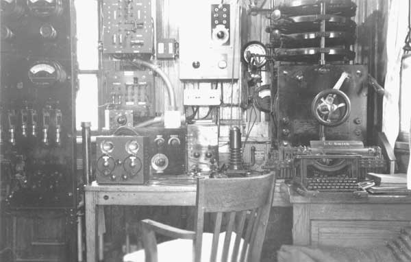
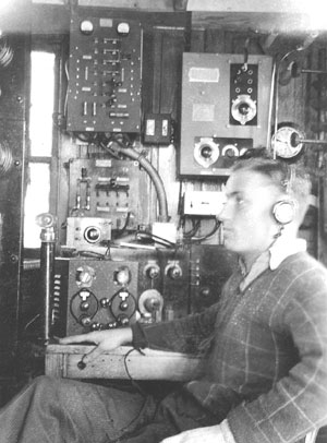
| The first picture shows the
earlier setup. No doubt, some of this equipment was installed when
the ship was built in 1919, or soon after. At the far right is a quenched gap
"Navy Standard" 2 KW spark transmitter,
and on the table (partly obscured) is an early receiver tuner with a detector/amplifier unit to its right.
The tuner appears to be an early 1920's GE model AR-1529, however, the
detector/amplifier cannot be identified. In front of this
equipment appears to
be a 1930's vintage receiver using plug-in coils, probably for short
wave reception. The large rack at the far left is the power
control panel for the transmitter. In 1921, the Marconi Wireless Telegraph Co. of America became part of RCA, as the Radio Marine Corporation of America (RMCA). On the original photographs, RMCA markings are just barely discernable on this unit. On the wall just above the receiver is a battery charging panel which can also be identified as an RMCA unit. Considering the presence of RMCA equipment, it is reasonable to assume that the spark transmitter is a Marconi unit. The small box on top of the earlier receiver is an RMCA type B receiver. This is a primitive set using a cat's whisker crystal detector and, as such, required no power for operation. Receivers of this sort were required by the government as a safety-related backup system that would remain functional in case of a total power failure. At the top center of the photo, mounted on the bulkhead is an RMCA model ET-8003 transmitter, a 50-watt radiotelegraph unit that operated from 355 to 500 kHz. Spark equipment was obsolete in the 1930's, but was often retained for emergency backup use on commercial vessels, especially when budgets were tight. |
|
|
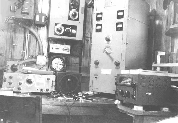
| In the later pictures, the
old spark gear is gone. A new RMCA model ET-8010-C transmitter is
seen where the spark transmitter had been. This was a 200 watt
unit that operated between 350 and 500 kHz.
To the right of the transmitter is a National NC-44 multiband receiver. On the desk is the speaker for the National, and an RMCA model AR-8503 receiver, a 4-tube regenerative design which operated in the range of 15 to 600 kHz. The RMCA type B emergency receiver is still present in this installation. Visible on the desk is a Vibroplex bug (semi-automatic key) for code transmission. |
|
|
 |
|
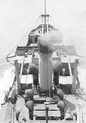
The Marsodak's antenna system. |
 |
|
The former owner of these photographs. |
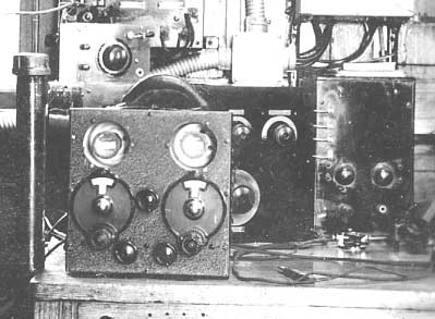 |
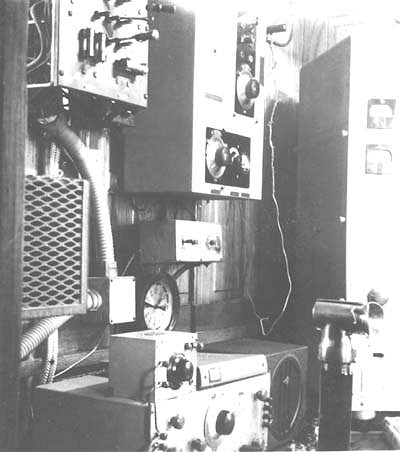
| Closeup of the receivers. |