|
Marti Model 2R10 |
||
 |
||
| This is the model 2R10
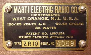
made by the Marti Electric Radio Company of East Orange, NJ, in
1927. This company was in operation from 1926 through 1929, when
it went bankrupt (just before the stock market crash). It was
reorganized as the Marti Radio Corporation, and operated briefly under
that name, but disappeared shortly thereafter, a victim of the
Depression.
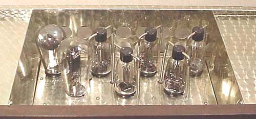
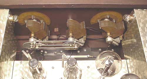
This radio is unusual for a number of reasons. It is one of the earlier AC-powered sets, and one of the few that used the McCullough/Kellogg type 401 tube (introduced in 1925). These unique tubes had heater connections at the top and, in this set, the connections are made through springs. The set also used a UX-210 as the audio output and a UX-281 as the rectifier. |
||
 |
||
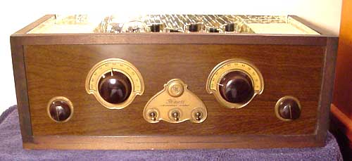
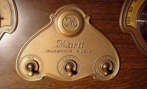
| All Marti's were
distinguished by the engine-turned decorative panels. These are
thin sheets of aluminum that were repetitively polished by a circular
tool to produce the swirl effect, and then coated with a clear lacquer
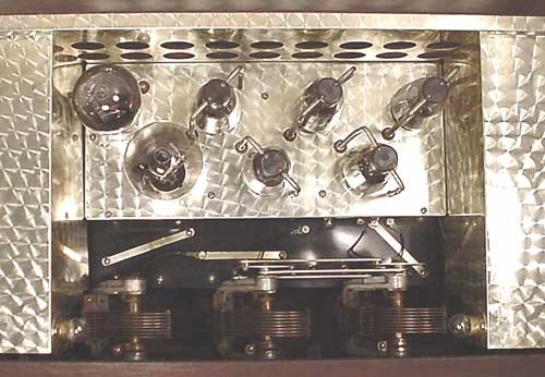
for protection. The two pieces on either side hide the power
supply components. The piece at the base of the tubes is not a
chassis in the normal sense, nor is it purely decorative. It
serves as the means of distributing heater power to the McCullough tubes
and is about 1 1/2 inches above the actual chassis (a sheet of black
Bakelite).
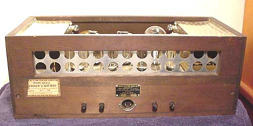
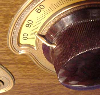
The front panel is aluminum, with a painted wood grain finish. The tuning capacitors were made by Hammarlund. The two on the right operated in tandem through an ingenious linkage system. The tuning knobs had needle-sharp pointers machined from brass rod stock, and the dials were illuminated from behind. The set shown here, is made of a cheap grade of wood, stained to a dark color, without a finish coat of varnish or lacquer. It never had a lid. It was meant to be an insert for a console cabinet, which would also have housed the speaker. Though the nameplate on the back shows it as a 2R10 (which was a table model radio), an additional model number (SC10) is stamped on the cabinet. This would have been the model number of the complete console radio. |
||
 |
||
 |
||
|
The circuit is quite conventional for the day. It used two tuned RF amplifiers, a detector, and three stages of resistance-coupled audio amplification. The power requirement for the output tube is extreme, requiring about 450 volts on the plate. It does have very respectable power output and has good sensitivity, but it is prone to oscillation. While it was advertised as an "all electric" radio, it still needed a 4.5 volt "C" battery to provide a bias voltage to the McCullough tubes. This battery was to be replaced every 6 months, according to the sticker on the back. |
||
 |
||
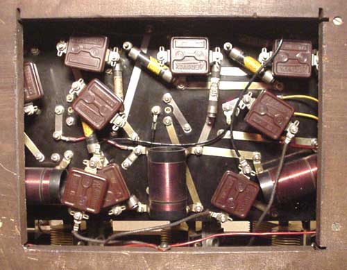
| Service men must have hated
this radio. The following note appeared in Volume 4 of the Rider's
Perpetual Trouble Shooter's Manual:
"Numerous requests have been received for circuit diagrams of Marti receivers. It has often been repeated by service men that many changes were made in these receivers and that no two of them are alike in every respect." It is a difficult set to work on as it is necessary to disconnect numerous wires from both the top and bottom of the chassis before it can be removed. Once the chassis is out, it is impossible to operate it as most of the power supply components remain mounted to the inside of the cabinet. Unlike almost every radio before or since, the Marti has virtually no soldered connections internally. In fact, the only solder joints are where the RF coil wires are joined to the terminals. All other connections are made by lugs crimped onto wires, or by strips of nickel-plated brass, joined by bolts and nuts. These sets had problems with poor connections which caused low volume and oscillation. |
||
|
|
||
 |
||
 |
||
 |
||