| 1930 Prototype AC/DC Radio |
 |
|
One of the lures of any collecting field is the prospect of stumbling upon some unique, one-of-a-kind treasure. This radio certainly qualifies as unique, and it's definitely one-of-a-kind, though it might not be a treasure in the usual sense. In the early years of the 20th Century, depending on location, the power supplied to peoples' homes might have been AC or DC, and the AC line frequency could have been 25, 50, or 60 Hz. Light bulbs and electric heaters don't care what kind of power they operate on, but most other electrically-operated appliances do, and as they proliferated, manufacturers had to face the issue of dealing with multiple (and incompatible) power sources. Throughout the twenties, radio design was evolving rapidly. The market demanded line power operation, rather than short-lived, expensive, and messy batteries. To meet this demand, radio manufacturers had to provide specially designed radios for DC areas, and modified versions of 60 Hz AC radios for 25 Hz areas. Obviously, this was an expensive proposition, and they sought a way to build a universal home radio, one that would operate on any type of line power. Eliminating the power transformer was the key, and without that heavy and expensive component, size, weight, and cost could also be reduced. That key opened up the whole house to the radio. Small, light, and cheap radios could find their way into bedrooms, workshops, garages and kitchens. The manufacturers were eager to build them, and the consumers were eager to buy. What you see here is an experimental radio that would be able to work on AC or DC power. It was most likely built in 1930. While it never would have been a marketable product, it served as a "proof of concept" design that was probably shown to company executives to gain approval (and funding) for future projects. In all probability, those future projects would have included the design of tubes more suited to radios of this type. |
 |
|
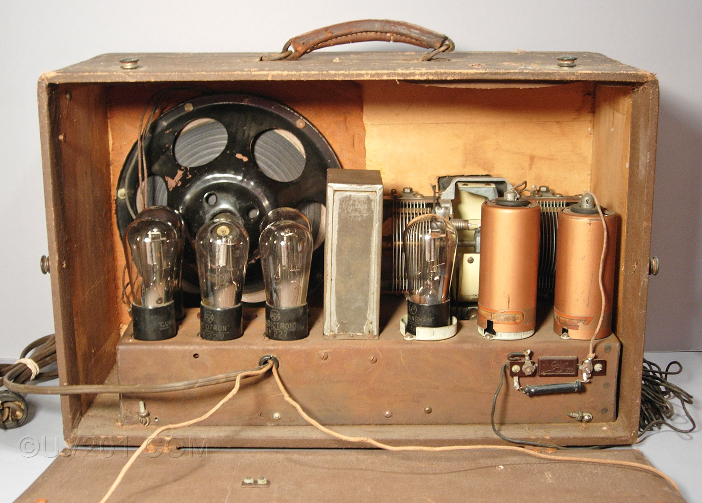
This 8-tube radio was designed around the only suitable tubes that were widely available at the time, the UY-227 triode, and the UY-224 tetrode. The problem they posed, however, was that they needed a lot of current at a low voltage to operate their heaters (2.5 volts at 1.75 amps). Providing that sort of power was easy with a power transformer, but without it, there was a problem. Putting the heaters in a series string was the solution, but in this radio, that meant 8 tubes at 2.5 volts, or a total of 20 volts, at the same 1.75 amps. To drop the standard (at the time) 110 volt line voltage down to the 20 volts needed by the tubes, a resistor was necessary. Because of the high current, this resistor had to be huge because it would have to dissipate about 150 watts in the form of heat. The power needed by the radio itself was only about 50 watts, but the power wasted in the resistor meant that it would be drawing 200 watts, total. Today's line voltage has been standardized at 120 volts plus or minus 5%. Where I live, the voltage is at the high end of this range. To operate this radio today (I haven't yet had the nerve to fire it up) that resistor would have to dissipate about 180 watts. No Energy Star rating for this one! The resistor is huge, and is mounted on the back of the radio in such a way that it could be partially opened to expose the resistor to outside air flow. |
 |
|
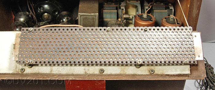
Resistance wire was wound on a strip of mica which was then sandwiched between two more mica sheets. This assembly was then encased between two sheets of perforated steel, which provided mechanical stability and improved heat dissipation. The resistor is mounted on standoffs, about 1/2 inch from the plywood back of the radio, which allowed air to flow around it. To protect the cabinet from the heat, a layer of asbestos was added. The resistor is about 14 inches long, and 3 inches wide. It probably would not be a good idea to touch this resistor when it is operating-that would be about the same as putting your hand on a 150-watt light bulb. The first small commercially marketed AC/DC sets of the early thirties used four tubes. Typically, they used type 36, 37, 38, and 39 tubes, all of which had 6 volt heaters and required 0.3 amps to operate. These tubes were originally developed for use in auto radios. In series, that meant that a resistor was needed to drop the 110 volts down to 24 volts, and the much lower current requirement meant that the resistor only needed to dissipate about 25 watts. One such radio appears here, and another here. The heat produced by this resistor was a problem in small sets. One solution was the so-called resistor line cord, in which this resistor was included as part of the line cord itself. These cords had a length of resistance wire wound around an asbestos core that ran along with the usual two conductors. This line cord would get hot in operation, and if not properly ventilated, could (and did) cause fires. They came to be called "curtain burners". Many of these sets came with tags that warned the customer to extend the cord fully so they would not overheat. Some sets had the resistor built in. This could cause problems with the cabinets that included cracking and discoloration of plastics, and charring of wood. Many of them had asbestos pads between the chassis and the cabinet to try to deal with the problem. Many sets used a so-called "ballast tube". This was nothing more than a resistor enclosed in a plug-in package that looked like a tube. The ballast tube had the advantage of being easily replaceable, and radio manufacturers almost universally included it in the tube count for the radio as an advertising ploy even though it contributed nothing to the performance of the radio. One remarkable radio sold under the Kadette name actually used three ballast tubes to pump the overall tube count up to 10. By 1935, the first tubes specifically designed for series string operation were on the market, typically requiring a total of 68 volts (still at 0.3 amps) for operation in a 5-tube set. Types 43, 25L6, 25Z5, and 25Z6 all had 25 volt heaters (the others were still 6 volt tubes). That meant that the resistor now had to dissipate only about 12 watts. An improvement to be sure, but this was still not the final answer, and it also meant that the tubes themselves ran hotter. By 1939, the typical 5-tube AC/DC radio used tubes whose heater voltages, in total, exactly matched the line voltage, so no additional resistor was needed, and the dreaded resistor cord was finally gone. These tubes only needed 0.15 amps for their heaters which further reduced the heat problem in small sets. Those tubes, the 50L6, 35Z5, 12SQ7, 12SK7, and 12SA7 were produced by the millions, and used in hundreds of models made by virtually every radio manufacturer. Their miniature brethren, the 50C5, 35W4, 12AT6 (or 12AV6), 12BA6, and 12BE6, were even more widely used. At this point, the design of the small AC/DC radio, now called an "All-American Five" had stabilized. With only minor changes brought about by improved tubes and components, this design persisted through the next 25 years or so, until solid-state designs pushed it aside. |
 |
|
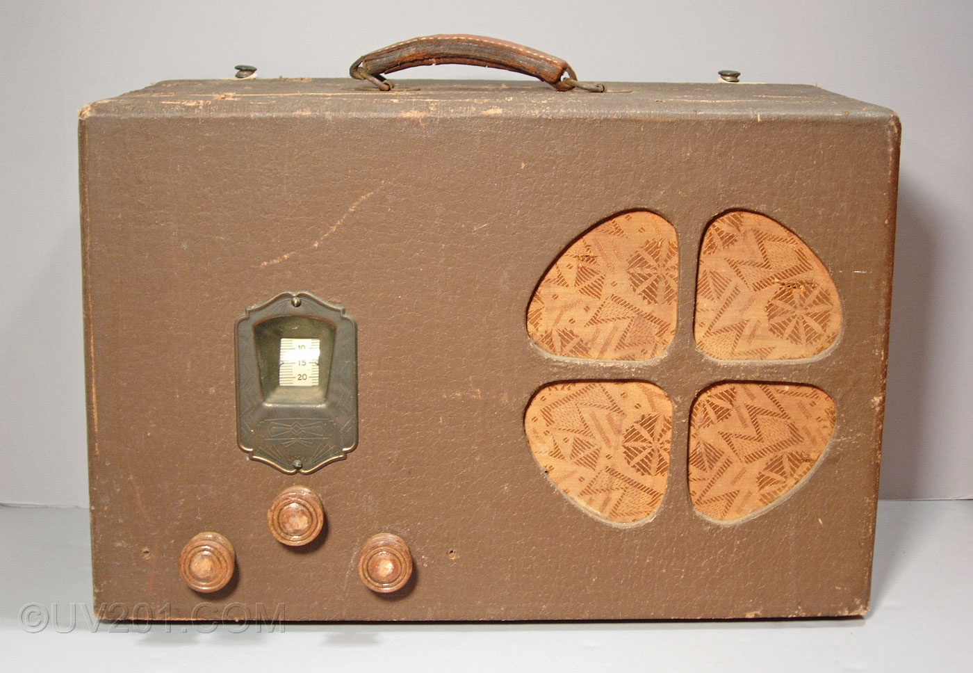
The circuit of this radio is straightforward, a typical TRF design of the day. There were two UY-224 tubes operating as RF amplifiers, a UY-227 served as the detector, another UY-227 served as an audio amplifier, and two UY-227's formed a push-pull audio output stage. Two parallel-connected UY-227's served as rectifiers. The cabinet is made of thin plywood with a fabric covering. It measures about 18 inches wide, 12 inches high, and 8 inches deep. The complete radio weighs about 20 lbs. Leather straps were originally provided to hold the back closed, but they have long since torn off. Obviously, little effort was made to create an attractive radio, but that wasn't it's reason for being. The Art Deco design fabric covering the speaker opening is a nice touch, though. |
 |
|
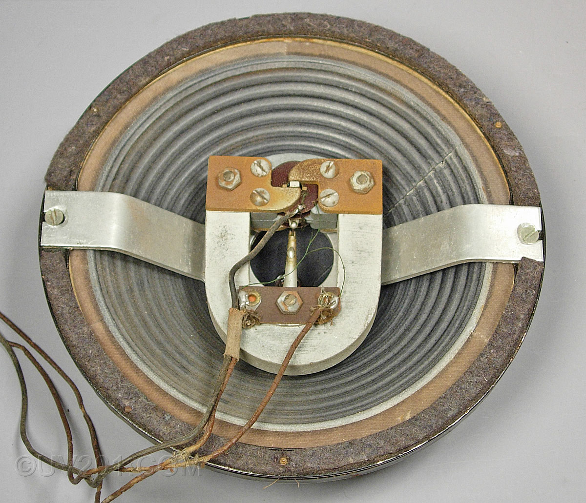
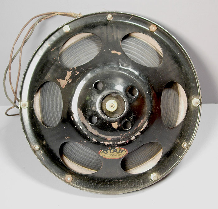
The speaker, made by Utah, is interesting. The design is typical of the late twenties, but it was rare for the driver to be mounted in front of the cone, rather than in the rear. The felt gasket around the periphery of the speaker has clearly been cut away to allow the driver mounting bracket to be bolted in place, which means this was a modification, probably for space reasons. It's not clear, however, how the driver would have been mounted from the rear, unless another bracket, now discarded, extended out to the outer rim of the speaker, but that was not the normal way drivers were mounted. The driver is definitely a Utah product, however. The shape of the pole pieces match a picture I found in a 1929 catalog. The high impedance driver uses two coils in series. The designers of this radio brought out a third wire which connected to the junction point between the two coils. This center tap allowed the speaker to operate in a push-pull mode without an output transformer. |
 |
 |
|
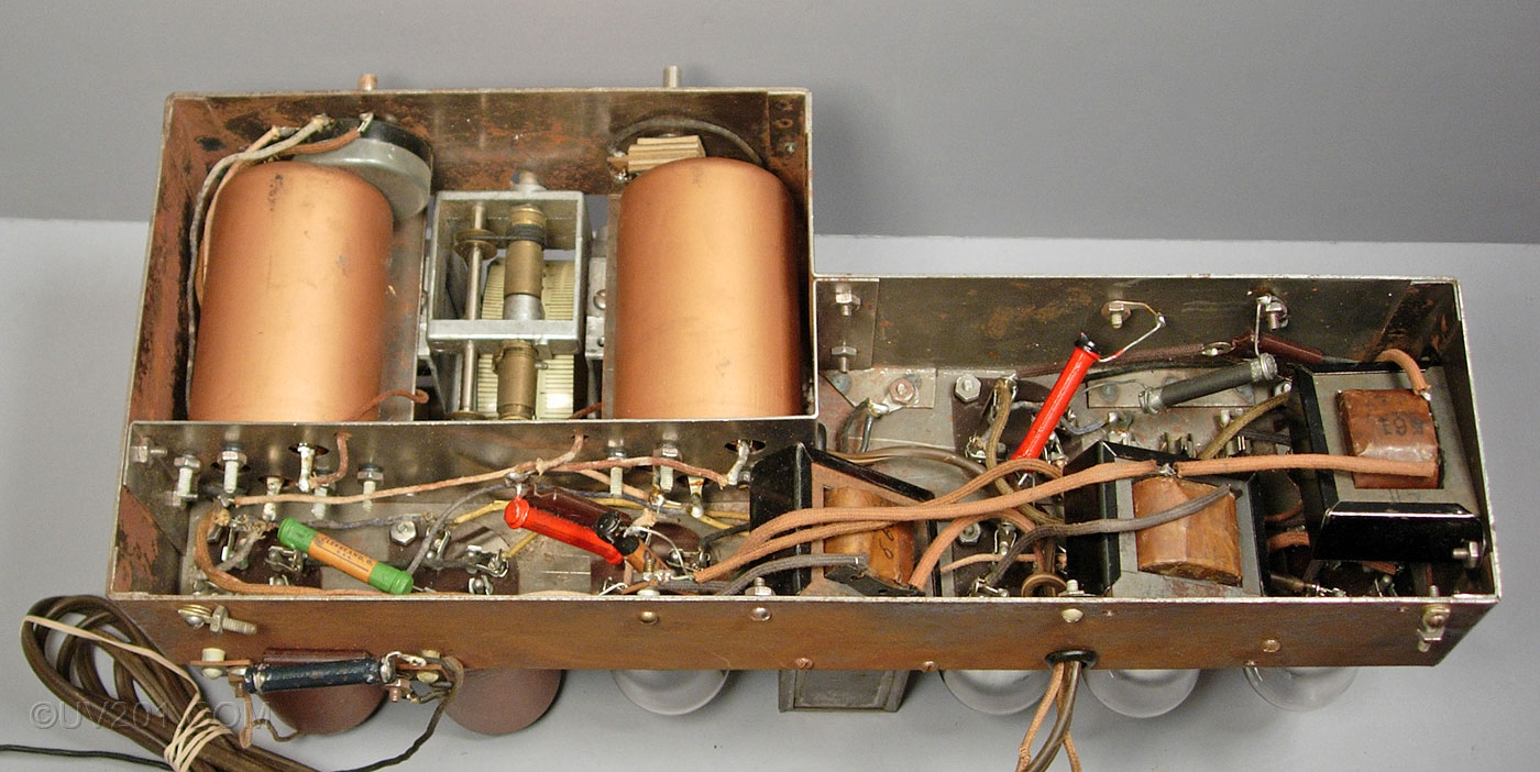
The underside of the chassis can be seen here. The construction and components are consistent with a circa-1930 design. Two shield cans hold the two RF coils, and two audio transformers and a filter choke are seen to the right. The chassis was fabricated from unplated steel sheet, and a number of separate pieces were spot welded together to form the completed assembly. All of the tube sockets were bolted to the chassis, rather than riveted. In most production radios, they used rivets to mount the sockets. Not visible in the picture, but obvious on close examination of the chassis, are scribe lines that were made as the chassis was laid out. A production chassis would normally be plated or painted to resist corrosion. On this prototype that was not done, and most of the exposed surfaces have a light coating of rust. So, it's obvious that this radio was not a production model, and was never intended for production. The chassis is too well made to have been somebody's home project, unless that person had serious metal forming tools and a spot welder. Establishing a date isn't too hard. The rectangular can in the center of the chassis containing filter capacitors has a paper tag on it. The tag gives the manufacturer as the Kellogg Switchboard and Supply Corp. of Chicago, and the date is November 27, 1929. So, the radio has to have been made after that date. There would have been no reason to make this set after the type 36 through 39 tubes were introduced in 1931, so 1930 is the probable date. The toughest question is "who made it"? The two tube shields that are with the radio (the third one is missing) have stickers taped to them which mention the Champion Radio Works, Inc. of Danvers, Massachusetts, a tube manufacturer. These stickers were of the type that would have been used by a dealer to mark the date of sale of a tube in case of a warranty return. Does this mean that Champion built this set? Or, could Kellogg have built it? |
 |
|
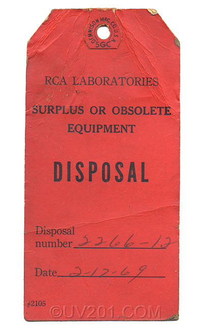
The most compelling clue is this tag was found inside the radio. It is from the RCA Laboratories that were located just outside of Princeton, New Jersey. The radio, of course predates the construction of that facility by more than a decade, but it appears that it found its way into a storage area there where it languished until a 1969 cleanout. Where it's been since then, I have no idea, but there is evidence that someone tried to get it working, and probably succeeded. The power cord has been replaced, and one of the UY-224 tubes had its loose grid cap reattached with epoxy glue. Of course, the fact that the tag was with the radio does not necessarily mean that RCA designed it. Indeed, the tag may not have anything at all to do with the radio. So, lacking any better information, I will say for now that this was an RCA product. If anyone out there has any information that would confirm or refute this, I would appreciate an email. |
| Home |