|
Western Electric Experimental Tube Collection |
||
| This page features a
fascinating collection of handmade experimental tubes which appear to
have originated within the Western Electric company, circa 1920. The base which appears on the first of these tubes is very definitely Western Electric, and is of a type that was used on production tubes from about 1917 through 1925. The base has no markings whatsoever, which means that it was not salvaged from an existing tube All production tubes using this base would have type number and patent information steel stamped into the metal shell. Only someone within the company would have had access to an unmarked base such as this. One of the tubes has a sticker on it with a late 1920 date clearly marked, and a reference to a laboratory notebook. If anyone has any information on these tubes, I would really like to hear from you! |
||
 |
||
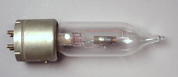
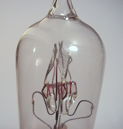
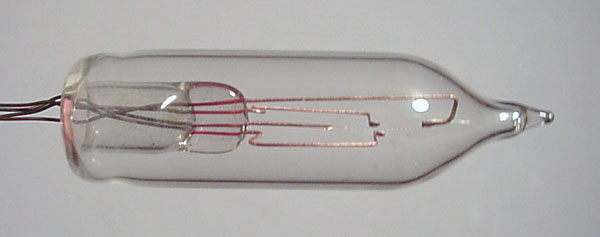
| This tube is a conventional
triode with a cylindrical plate, however, the construction of the grid is
unusual.
Most tubes of this general type and vintage used a single length of wire bent into a helical (spiral) shape that was supported at each end. In some cases, this helix was tied to a support rod to give improved stability. The grid in this tube was fabricated by welding a number of pieces of wire to a single support rod, forming a comb-like structure, and then bending them into a cylindrical shape. The grid may have originally been fabricated as a ladder type structure (as used in most WE production tubes), and then cut apart. All of the tubes in this group have very fine filament wires. It is known that Western Electric was trying to develop tubes with a much lower filament power requirement than was common at the time. This development process led to the 215-A "peanut" tube introduced in 1919. It is quite likely that the tube shown above is one of the developmental steps which led to this tube. A tube very similar to this one is illustrated in Gerald Tyne's book, Saga of the Vacuum Tube, figure 14-23. It is possible that the designers of this tube were investigating alternative grid fabrication techniques to overcome certain manufacturing difficulties that may have been encountered in attempting to build very small tubes. |
||
 |
||
 |
||
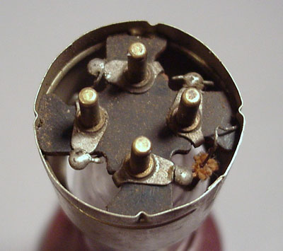
| In production tubes, the interior of the base was filled with a wax compound. There was no need to do this for a tube that would never be used outside the laboratory. | ||
 |
||
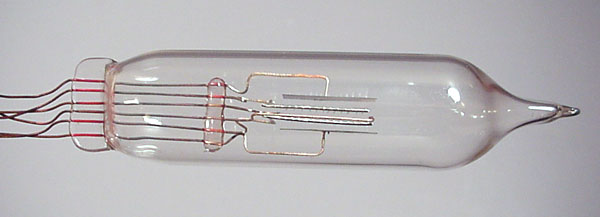
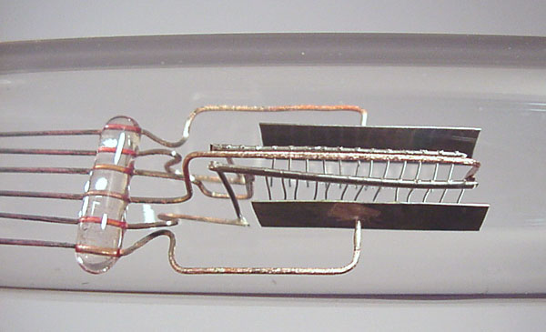
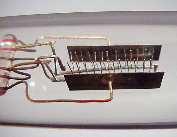
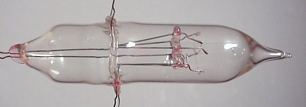
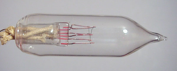
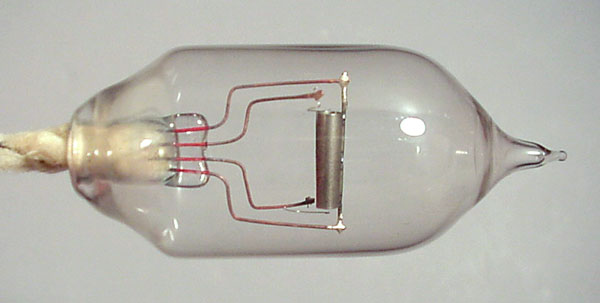
| The next tube
is a conventional triode type, with two plates, two grids, and a
single filament in between. Each grid and plate is provided with a
separate external wire lead. There is no special
significance to this feature; it was probably easier to build the tube
that way. As with the grid in the previous tube, these grids are comb structures, but are flat, rather than bent into a cylindrical shape. This tube is about 4 inches long (not counting the leads), and about 7/8 inches in diameter. |
||
 |
||
 |
||
| This side view shows the plate cut from a piece of metal sheet stock. | ||
 |
||
| This view clearly shows the comb-like grid structures, and the filament wire. | ||
 |
||
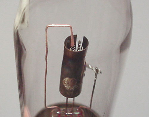
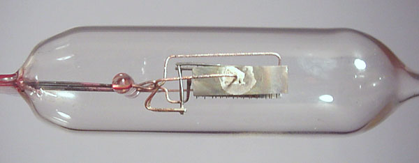
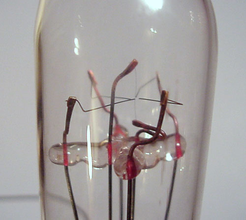
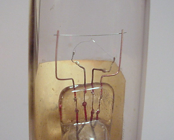
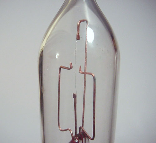
| The second tube is very
unusual. It has two comb-like grid structures similar to the first
two tubes, but
no plate in the conventional sense. A filament is positioned
between the two grids. The grid wires were carefully bent so
they were very close to the filament without actually touching it. The purpose of this structure is difficult to fathom, but I propose the following: Tube manufacturing in 1910's and early 1920's was complicated by the restrictive DeForest grid patent which specified that the grid had to be located between the filament and the plate. Many companies investigated alternative designs which would not infringe this patent by placing the filament between the control element (the "grid") and the plate. That may be what this and some of the other tubes in this group represent. Western Electric had, in 1912, purchased the rights to produce tubes from DeForest. The agreement, however, restricted them from using the tubes for any purpose other than low frequency telephone repeater service. In other words, they couldn't build tubes for radio applications. Western Electric was a major supplier of military radios and tubes during WW-1, and was able to bypass the licensing agreement with DeForest for the duration. After the war, the prewar restriction on radio tubes went back into effect. Western Electric apparently embarked on an R&D effort to develop and patent a non-infringing amplifier that would be suitable for radio use. This would have opened the door to the manufacture of radio tubes, and associated equipment, and would have put the company in a stronger position in the marketplace by preempting their competitors. Note the broken glass at the center of the tube. Apparently, a burned out tube was salvaged by breaking the glass, and building the remains of the first tube into a new envelope after installing a new filament. This suggests that the designers saw some promise with this design. This tube is about 3 1/4 inches long, and 1 1/4 inch in diameter. |
||
 |
||
 |
||
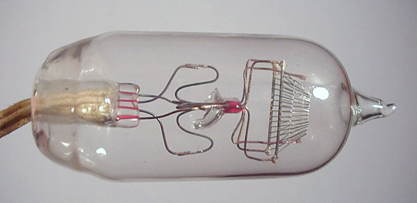
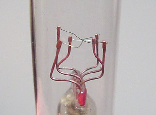
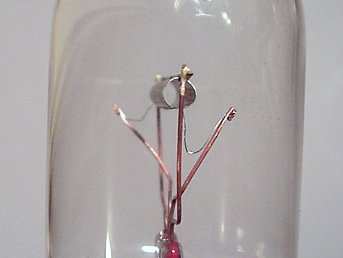
| The third tube is even
stranger. This may also be an attempt to build a gridless
amplifier tube. It has a short filament, oriented vertically
within the tube. Pointing to the filament, but not touching it,
are four wires which are connected to external leads. Two of these
leads were soldered together, suggesting that the designers were trying
different combinations of these wires to function as plate and control
electrodes. This tube is about 4 1/4 inch long, and 7/8 inches in diameter. |
||
 |
||
 |
||
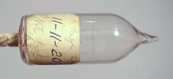
| This tube has only a
filament and a wire as the second element, and is the only one that can
be precisely dated. Of the group, it is also the only one that has platinum wire segments embedded within the press (the flattened glass part through which the external leads enter the evacuated interior. A critical issue faced by early tube (and light bulb) designers was the problem of air leakage through the press. Platinum wire was well suited for this purpose, as its coefficient of expansion closely matched that of the glass, but was very expensive. It was replaced by Dumet, a copper-clad nickel-iron alloy, which was much cheaper and had the required expansion characteristics. Dumet was introduced in (or about) 1913, and by the time this tube was made, it had almost entirely replaced platinum for this application. Copper (or copper-clad) wire inside the press will show a distinctive red color. Platinum will have a silver color. |
||
 |
||
 |
||
| This tube appears to be still another variation on the gridless amplifier theme. There are two wire elements crossing each other at right angles, and between them is the filament. | ||
 |
||
 |
||
| Still another gridless amplifier, this tube featured two tiny hand-like elements on either side of the filament. Several other tubes in the group were variations on this theme, with different positioning and construction of the "hands". | ||
 |
||
 |
||
| The last tube in the group is a fairly conventional diode with a cylindrical plate. This tube measures about 3 inches long, and is about 1 1/4 inch in diameter. | ||
 |
||