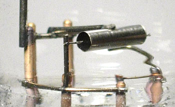
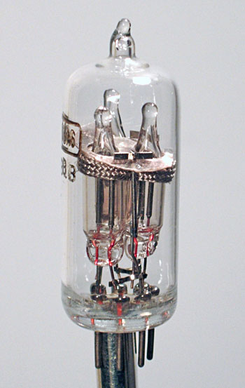
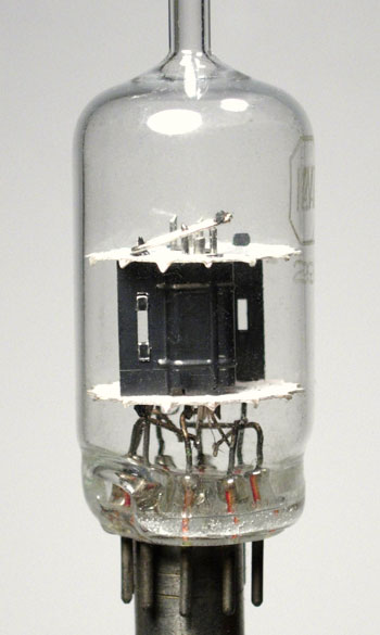
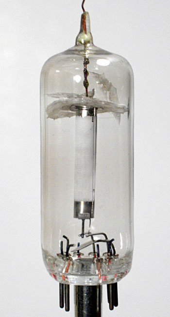
| This odd tube has a
structure very similar to common dual-diode-triode tubes such as the
6AV6 and 6AT6, but it is contained in a Loktal envelope. There
were Loktal tubes of this electrical configuration (e.g. the 7C6),
but they did not resemble this one physically. The two vertical metal elements at the left side in the picture seem to have no discernable function, but yet they are connected to pins at the bottom. The cylindrical section in the center is normally a triode, but no grid was ever installed in this tube. I suppose that doesn't really matter, because no electron-emissive coating was ever applied to the cathode, and the tube was never sealed. What's more, there weren't enough pins on the bottom to accommodate all of the elements inside. The cathode is connected to one side of the heater, something that would not be done in a production tube. So, it would appear that this was never anything more than a mockup of a tube that was under consideration. |
 |
|
|
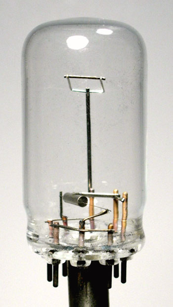
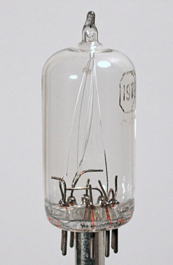
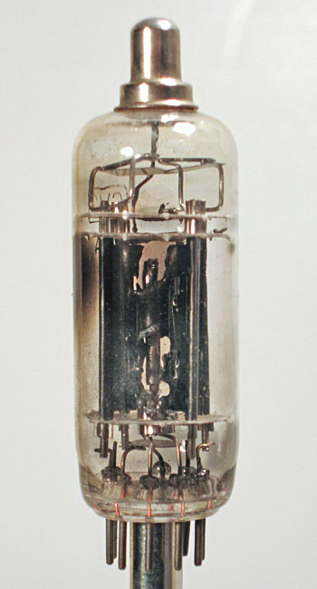
This strange device
is not a tube in the normal sense. It contains three standard
NE-2 neon bulbs wired to the pins on the bottom. Two
electrodes are positioned to affect the firing characteristics of
the bulbs in whatever application it was intended. A piece of
fiberglass sleeving is wrapped around the bulbs to keep them in
position. Neon bulbs can be used in oscillator, triggering, and counting applications, though they aren't particularly stable. This "tube" may have been used (or at least tried) in one such circuit. |
 |
|
|
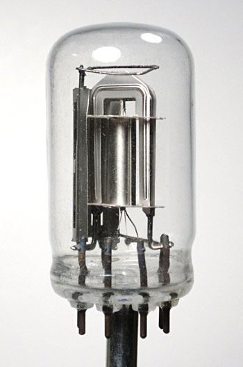
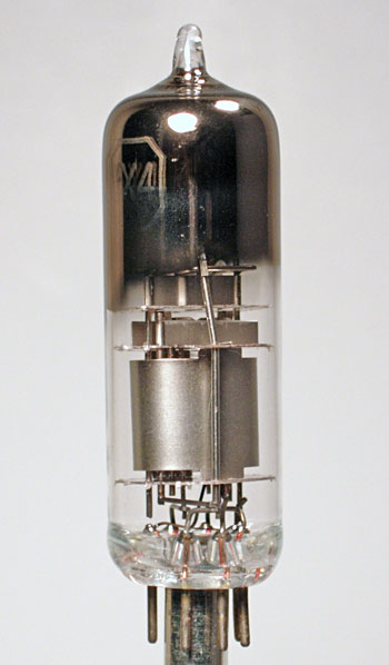
This tube consists of
a single diode in a Loktal envelope (without the metal base shell).
From the size and construction of the elements, it would appear to
have been meant for a battery powered application. This
tube was never evacuated and sealed. It does not correspond to
any production tube that I am aware of.
|
 |
|
|
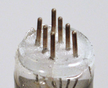
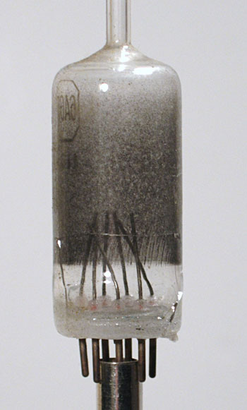
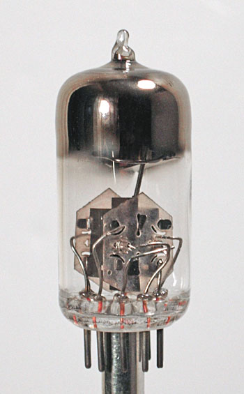
This
strange tube is marked as a 6BA6, but it actually contains nothing.
What is interesting is the base. The standard miniature tube
base was either 7 or 9 pins in a circular pattern. Apparently,
Philco was considering an alternative pin layout. I have no
idea why. The dark coating inside was used on a number of
different tube types.
|
 |
|
| This tube appears to be a production line error. The tube is marked "6X4" (a rectifier tube), however the internal structure is that of a 1R5, a widely used battery radio tube. The 1R5 should have a bulb that is about 1/2 inch shorter than that of the 6X5. So, this is either a 1R5 with the wrong bulb, or a 6X5 with the wrong internals. |
 |
|
|
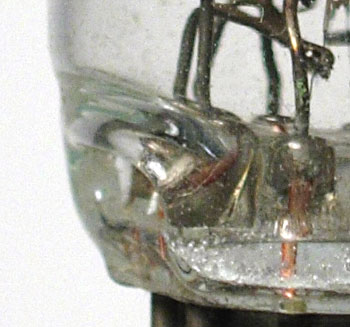
This
12AV7 dual-triode also appears to be a production-line reject.
The process by which the glass base was joined to the tubular
section was unsuccessful, as a hole developed (as seen at the left
of the base area). It may have been a problem with temperature
control.
|
 |
|
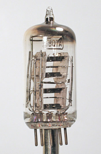
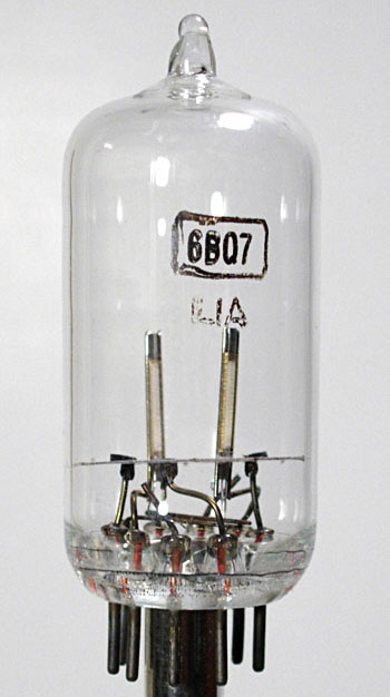
| This oddity contains four triode sections, but they are internally connected in parallel, so it would function as a dual-triode. It has the same pinout as the production 6BQ7 and 6BZ7 tubes (and several other similar types). Such tubes were designed expressly for high frequency use, so the structures are very small. Perhaps this design was being tried to increase the power handling capacity without limiting the high frequency response. |
 |
|
 |
 |
|
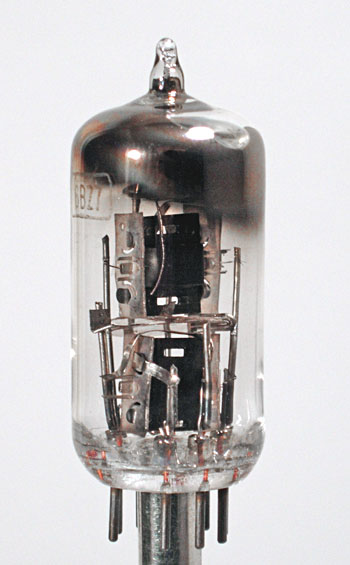
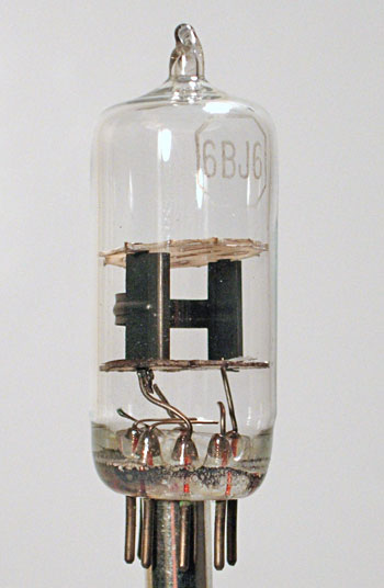
| These tubes are further variants on the dual-triode theme, of the 6BQ7 and 6BZ7 type. The Philco engineers apparently tried a side-by-side horizontal orientation of the internal structures (left) and an "over and under" configuration (right). The production tubes always used a vertical orientation, so it might be inferred that these variants were no better, or even worse. | ||
 |
 |
|
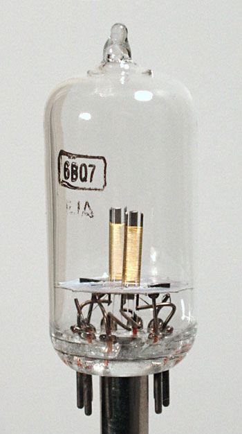
| The four tubes above and below, were deliberately constructed with only portions of the complete structure in place. They may very well have been made for use in displays. The tube above and to the left contains only the heater. The one to its right contains only the plate. Incidentally, it does not bear any resemblance to the plate of the 6BJ6. It is actually that of a 6CB6 (or any of several similar tubes). The tube below and left has only the heater and cathode elements. The tube to its right adds the grids (note the gold-plated grid wire). | ||
 |
 |
|
 |
 |
|
| These are 6V3 tubes which were intended for damper service in television receivers. The tube on the left, for whatever reason, has only the heater and cathode elements installed. The mica spacer at the top has flaked apart. The tube on the right is a production tube that has been subjected to severe testing and has suffered a meltdown. The entire cathode cylinder has disappeared, revealing the heater that is normally hidden. The plate has been seriously damaged. | ||