| Early Ham Radio Photographs-Page 3 |
 |
|
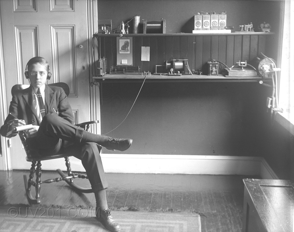
This wonderful old photo shows a young ham radio operator listening intently to a transmission. The boy looks to be about 15. The resolution isn't good enough to read the calendar on the wall, but my guess would be no later than 1912. Click on the photo for a larger version, and here for a close-up of the equipment shelves. Sadly, the quality of photo is not great, and the parts of the image at the far right are quite blurry. Significant is the lack of any indication of call sign, or a license. The first legislation requiring such formalities was passed into law in 1912. Before that, the airwaves were pretty much a free-for-all. The equipment is quite primitive, but you can see the components of a complete transmitting and receiving station. It's quite neatly done, but he must have used a higher stool for regular operation. The low rocking chair was probably just for the photo. On the bottom shelf, from left to right, you can see a sliding plate variable condenser. This exactly matches one that was advertised in early Electro Importing Company catalogs. Moving to the right, you can see two different loose couplers (receiving coils), and between them are a pair of binding posts to which the earphones are connected. There is probably a condenser there as well. In front of the second loose coupler is a crystal detector. The cat's whisker is clearly visible in the larger versions of the photo. Continuing to the right, barely visible, is a transmitting key, and to it's right, a spark coil similar to what was used in early automobiles. Next is a wood-cased transmitting condenser, and on top of that is a spark gap. Finally at the far right, is a transmitting helix (inductor). Wires lead from this through the window (under the sash) to the antenna and earth grounds. A knife switch is provided, most likely to ground the antenna for lightning protection. On the top shelf, above the spark coil, are four "Red Seal" batteries. These are the power for the transmitter. So, this is a very low-power operation, with a transmitting range of no more than a few miles. A spark coil very much like this one can be seen here. In front of the batteries is another knife switch, probably unconnected, and then a telegraph sounder and relay. These don't seem to be in use, either. To the left of the batteries are another receiving coil, several other objects including one that looks like a small artillery shell (a flashlight, perhaps), and at the far left, another transmitting key. A calendar hangs on the wall, and to it's right, a handwritten page showing the International Morse Code. |
 |
|
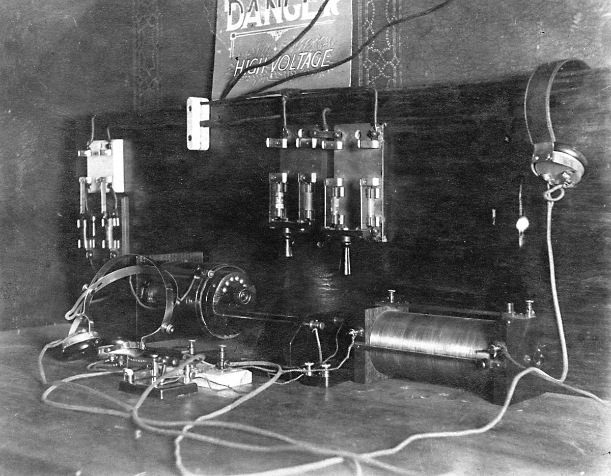
This picture shows an amateur receiving station circa 1916. There appear to be two complete receivers. One consists of a tuning coil to the right, what might be a crystal detector on a white porcelain base, and the pair of headphones hanging on the backboard at the top right. The second receiver is slightly more advanced, and consists of a loose coupler at the left rear, a crystal detector on a black base (a Bunnell "Jove"), and the pair of headphones at the left. Between the two coils is a phone condenser mounted in a black Bakelite housing. There are several knife switches mounted on the backboard, with integral fuse holders (note the warning sign). These must have been for a transmitter but there are no transmitter components visible in the picture. Those may be located elsewhere, though the transmitting key would surely have been located on this table. It's possible that this picture was taken during the WW-I period in which all amateur radio activity had been banned by the U.S. government, and the transmitter may have been dismantled. |
 |
|
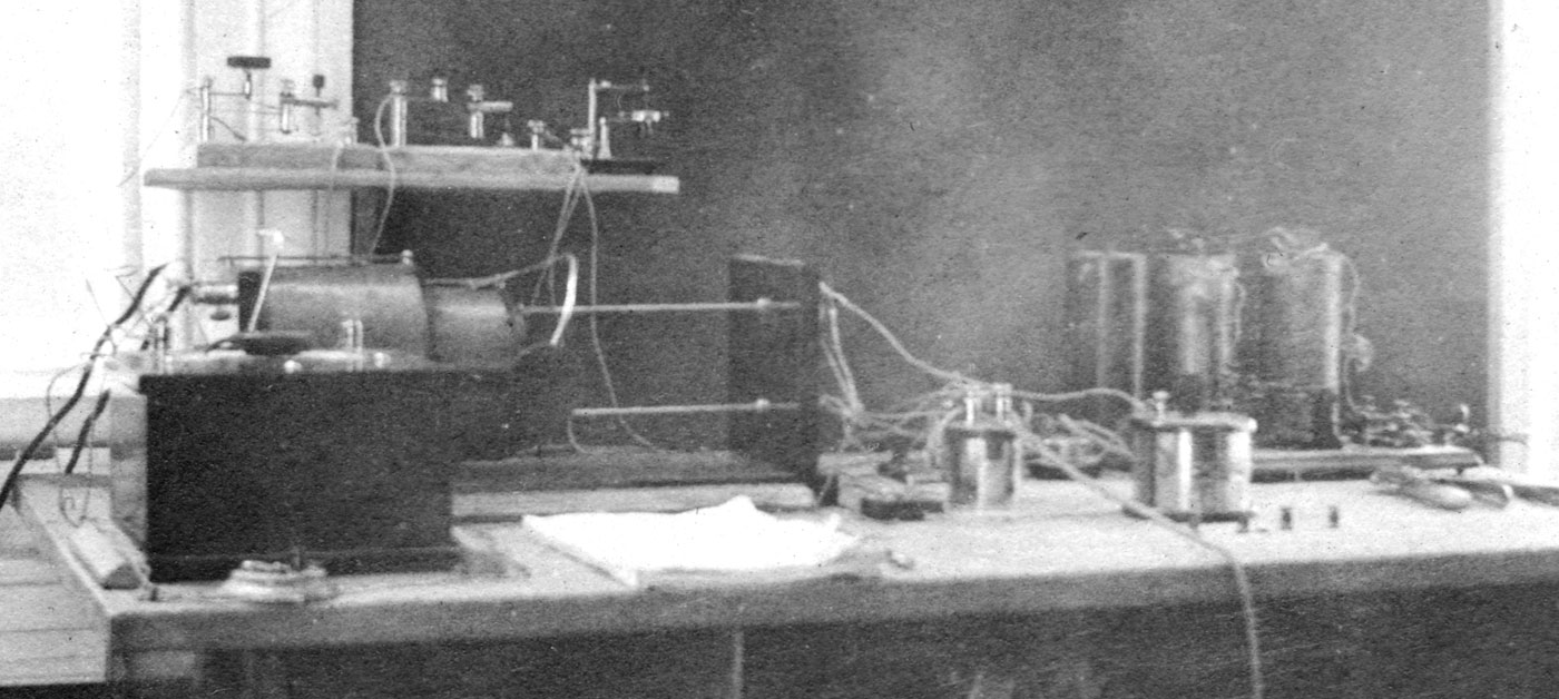
I believe this photo was taken at Princeton University, circa 1915. Unfortunately, the quality is very poor, but it shows a classroom demonstration setup with a radio receiver at the left and, possibly, a transmitter at the right. The large box at the front left is a variable condenser. Behind it is a very large loose coupler which would have been suitable for a long wavelength reception. On the shelf above the loose coupler are three crystal detectors. The two on the left are mounted on marble bases. They appear to be almost identical, and may have been made or sold by the J. J. Duck company. The one on the right is on a Bakelite or hard rubber base, as yet unidentified. The apparatus at the right is harder to discern. Mounted on a board at the far right is a telegraph key, and to its left may be a sounder. Behind it are three upright cylindrical objects which can't be identified. They could be batteries, but no markings are visible. They could also be coils, perhaps part of a low power transmitter. Toward the front of the table is what looks like an enclosed variable capacitor typical of those made by Murdock or Clapp-Eastham. Hanging from the right side of the table are two pairs of headphone. Click here, or on the picture for a larger view. |
 |
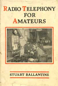
| This picture was scanned
from the photograph on the rarely seen dust jacket of the 1923 book "Radio
Telephony for Amateurs" by (Charles)
Stuart Ballantine (published by the
David McKay Company). Click
here, or on the picture, for a larger view.
The station in the photo is that of David Asbury, 3ADT, of Oak Lane, PA (a section of Philadelphia). Several pieces of equipment may be identified. To the very right (on the table) is a Westinghouse RA/DA receiver, and to the left of the operator is a homebrew transmitter. Just above his head are two horn speakers. The small one on the right is an Arkay, and to the left is a large homebrew horn. Behind the Arkay horn is another receiver, probably homebrew, using plug-in honeycomb coils (resembling donuts) in sets of three. These coils were probably made by DeForest. Additional coils are stored on top. On the wall is a Murdock antenna switch (click and scroll down), and power transformers for the transmitter. |
 |
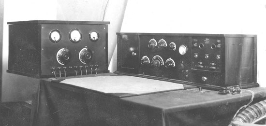 |
| This photograph appeared
in the October 1924 issue of Radio News magazine (page 491). This
image was, however, scanned from an original print. The article in
which it appeared was authored by a Paul G. Watson (ham call 4XX) of
Savanna, Georgia. It described the design of a radio receiver
which was located in the unit to the right. To the left is what
appears to be a transmitter, though it isn't mentioned in the article.
There is a transmitting key at the far right. The author notes
that the audio amplifier portion of the receiver was a converted
commercial unit. It appears to have been a Grebe RORK two-stage
amplifier. The transmitter appears to have no support under it and the cloth covering the table would have make operations difficult, so this must have been a temporary arrangement so the photograph could be taken. As it appeared in the magazine, the open area under the transmitter was darkened so it wouldn't look like it was floating on air. |
 |
|
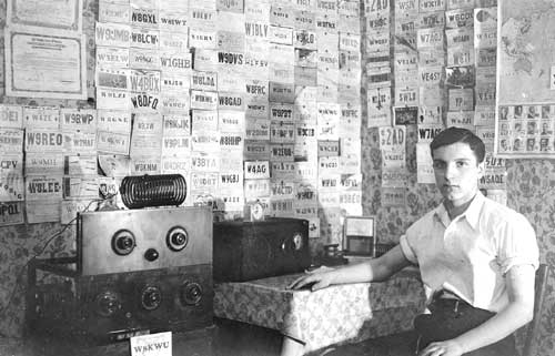
W8KWU-1936-All equipment appears homebrew. |
 |
|
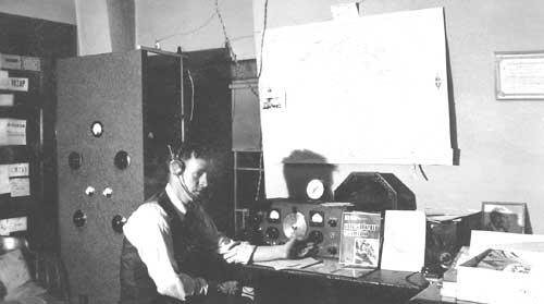
W8NEU-1938-The receiver is a Hallicrafters SX-16. |
 |
|
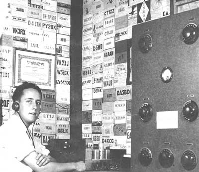
W3ERD-1938 |
 |
|
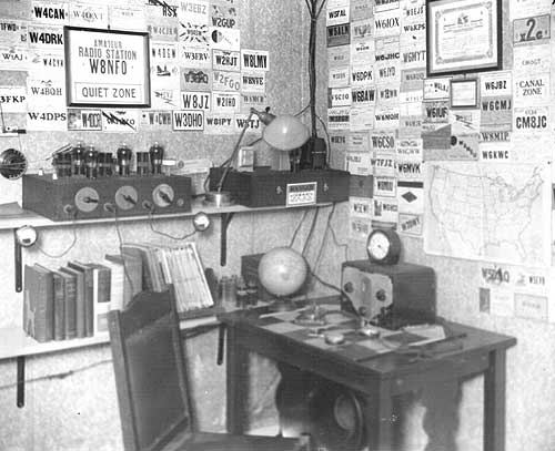
W8NFO-1935 |
| Home |