|
WESTERN ELECTRIC SCR-68 AIRCRAFT TRANSCEIVER |
 |
|
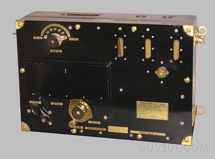
The SCR-68 was a radiotelephone transceiver (transmitter/receiver) that was made in 1918 by Western Electric for the US Army for use in airplanes. At the time, "airplane" meant an open cockpit, two-seat biplane. In typical military parlance, "SCR" meant "Set, Complete, Radio". The transmitter section used two type VT-2 tubes as oscillator and modulator. Either of two single-button carbon microphones could be used for transmission. The paddle at the lower left operates the transmit/receive switch. The switch at the top, and the knob at the bottom determined the receiver frequency. Three windows allowed the filaments of the three VT-1 tubes in the receiver section to be observed while in operation. Below the windows is a switch which controlled the receiver audio level. The receiver consisted of a non-regenerative detector, and two stages of audio amplification. The antenna was a long wire that trailed behind the airplane in flight. A hand-operated reel was used to extend and retract the antenna, which could be as long as 300 feet. It operated at a wavelength of about 400 meters (750 kHz), and the transmitter radiated power was about 0.75 watts. The range for reliable operation was only a few miles. Integrated with the radio set was an intercom system that allowed the pilot and observer to converse via microphones and headphones (rather than shouting over the noise of the engine and the wind). This unit measures about 17 by 11 by 7 inches, and it weighs about 21 pounds. About 3000 of these units were produced. They were introduced into service in the summer of 1918, only a few months before the end of the war. |
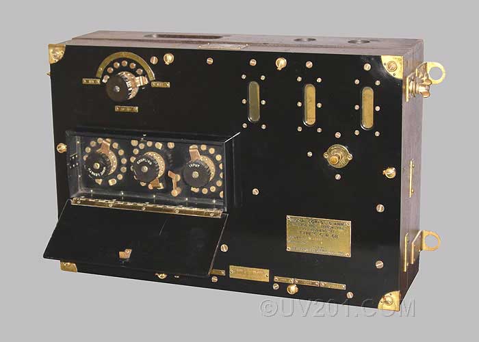 |
| A hinged safety cover conceals four switches which would have had about 275 volts on them when transmitting. The three rotary switches control the operating frequency and efficiency of the transmitter. The single-pole switch disables the modulator while tuning the transmitter. Two phone jacks at the bottom allow the oscillator grid and plate current to be monitored. |
 |
|
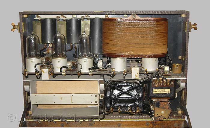
This picture shows the interior of the SCR-68 with the clamshell case opened. The three VT-1 tubes can be seen to the left. The two VT-2 tubes are located inside the large coil at the right. There was no technical reason to do this; it made for a lighter and more compact package. To the right of the coil is a smaller socket, which would have held a ballast (current regulator) lamp for the filaments of the VT-2 tubes. The three black cylindrical objects are audio-frequency chokes (Western Electric would have called them "retarding coils"). At the lower right is a battery compartment for three 22 1/2 volt "B" batteries. To the right of this are two capacitors encapsulated in tar, and hidden behind this assembly is the tuning capacitor for the receiver. At the far right is the microphone transformer and the transmit/receive switch. |
|
|
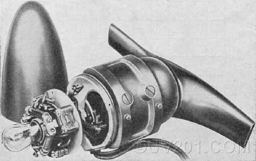 |
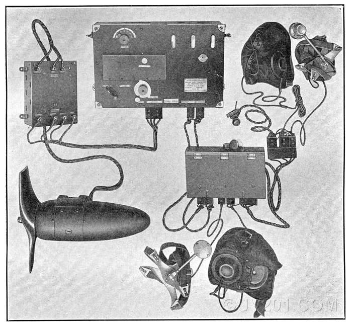
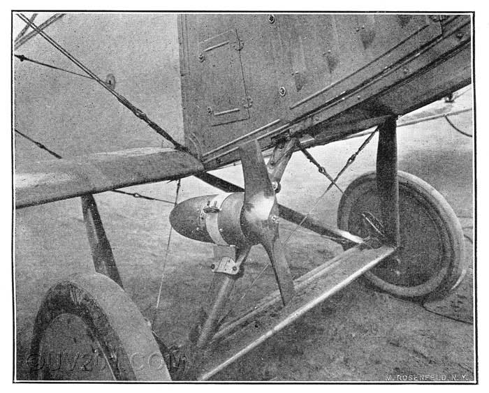
| The filament and transmitter plate supply voltage was provided by a wind-powered generator that was mounted on the landing gear struts. The voltage output was regulated by a General Electric type TB-1 vacuum diode which controlled the amount of current flowing through the generator field winding. Two 22 1/2 volt batteries provided plate voltage for the receiver tubes, and a third 22 1/2 volt battery provided grid bias for the modulator tube. The current supply for the carbon microphones was provided by batteries which were located an external interphone (intercom) control box, which was designated as the SCR-57. |
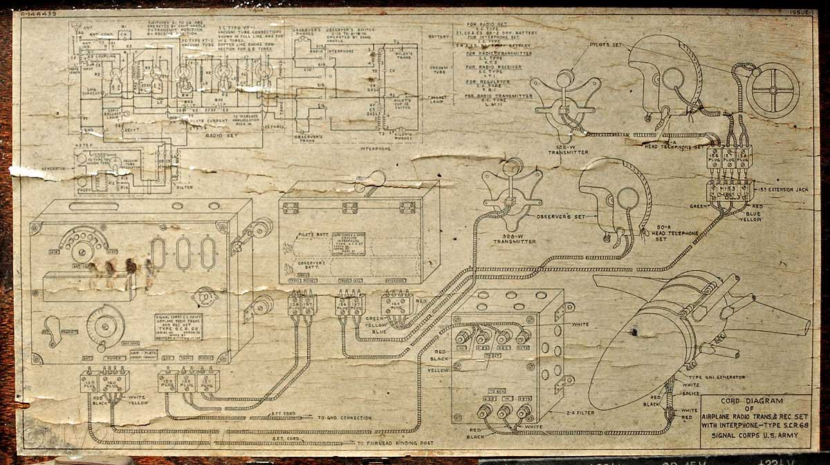 |
| A welcome
feature of this set is the detailed system schematic diagram that is
glued to the inside back of the cabinet. It shows the SCR-68
itself, the intercom control box, a junction box, two
operator's stations (pilot and observer), the wind-powered generator,
and the antenna reel. Click
here, or on the
picture, for a larger view. A four page article describing the SCR-68 appeared in the May, 1919 issue of "The Electric Journal" magazine. It may be seen (in .pdf format) here.
|
 |
|
|