|
1928 Marti Console |
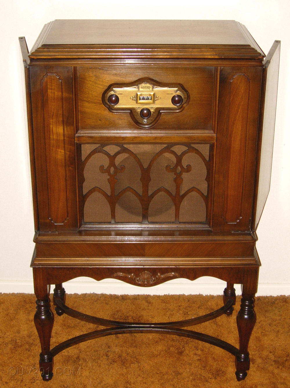 |
| This unique console radio
was introduced in 1928 by the Marti Electric Radio Company. The
model number is unknown, and it was advertised only as the Marti
Console. The list price was $350.00, less tubes (which would have
added another $50 to the price). That was serious money in 1928,
and would be equivalent to al least $4,000 today. This is a later model than the Marti 2R10,
and a much improved design. The company was formed in October, 1926, under the leadership of Charles Louis Marti, a Swiss citizen. The factory was located in West Orange, NJ, which was also the location of Edison's laboratory and they maintained a sales office and show room in New York. Marti radios were sold primarily on the East Coast. A few years earlier, Marti's first company, the Martian Manufacturing Company, built and sold several quirky (and very collectible) crystal-detector and one-tube radios. The best known of these is the Martian Big 4 radio which stood on a tripod base, and had connections for four sets of headphones. The formation of the Marti Electric Radio Company marked a major change in market strategy, as they moved into the fledgling market for AC line-powered radios that was developing in the mid 1920's. Nothing they produced was ordinary, and that's probably why the company was gone within a few years. They were not the first to produce a "socket power" radio, but they were certainly one of the first to use tubes specifically designed for AC operation. Marti was in receivership by September, 1929 and was reorganized in a last ditch effort to survive, but the market crash killed what was left of the company. These radios were expensive, not widely distributed, and were said to be flaky and troublesome. They didn't sell well and are extremely rare today. No production numbers exist, but I suspect the total production by the company was only in the thousands. (Note: Most of the pictures on this page are linked to high resolution versions. Click to enlarge.) |
 |
|
Electrically, this radio was a conventional 8-tube TRF (tuned radio frequency) design. It used three RF amplifier stages, a detector, and three stages of audio, with RC (resistance/capacitance) coupling. The audio output tube was a UX-210, the rectifier was a single UX-281, and the remaining tubes were Kellogg 401's. This tube was introduced in 1925, and when the Marti company was formed, the introduction of the RCA UY-227 AC-powered triode (a single-ended tube that was very similar electrically to the Kellogg 401) was still 6 months away (May 1927). The UX-210 appeared in September, 1925 and the UX-281 appeared in May, 1927. They would have used a UX-216B rectifier tube before the upgraded, but equivalent, UX-281 appeared. The first AC Marti radios were advertised late in 1926, so at the time, the Kellogg tube was an obvious choice. The were still being used in 1928, long after the appearance of the UY-227, but switching to the more conventional tube would have meant a major change in the physical design. They did switch to the UY-227 for their 1929 (and final) models, which used a conventional sheet metal chassis. The unusual Kellogg tubes gave the Marti radio a unique appearance that was enhanced by the decorative machine-turned aluminum panels that lined the cabinets and covered the chassis. Most, if not all, Marti sets used these panels. |
 |
|
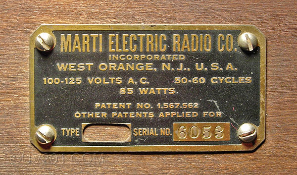
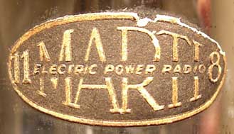
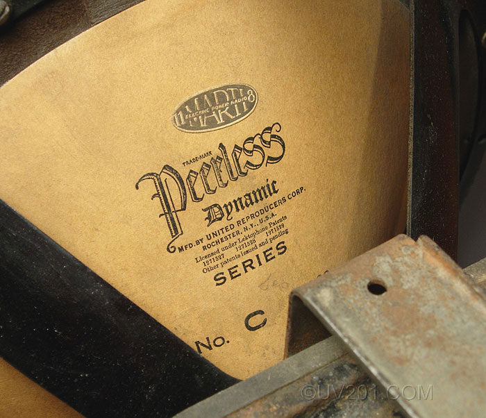
This nameplate appears on the back of the radio. What is particularly interesting is the space where the model number should have been. The plate was drilled out at the factory. I am aware of at least one other Marti with this cutout, so it was certainly intentional. They appear to have been using up existing plates to avoid the expense of having new ones made, hinting of a company struggling to survive. The nameplate on the Marti 2R10 is identical, except for the cutout. The four-digit serial number indicates a low production operation. The sticker shown below is on one of the tubes that came with the radio, and the same sticker is on the speaker cone. I would assume that all of the original tubes had these stickers. The numerals "11" and "8" appear on either end of the sticker. It is possible that the actual model number for this radio is 11-8 or, perhaps, 11R8. |
 |
 |
|
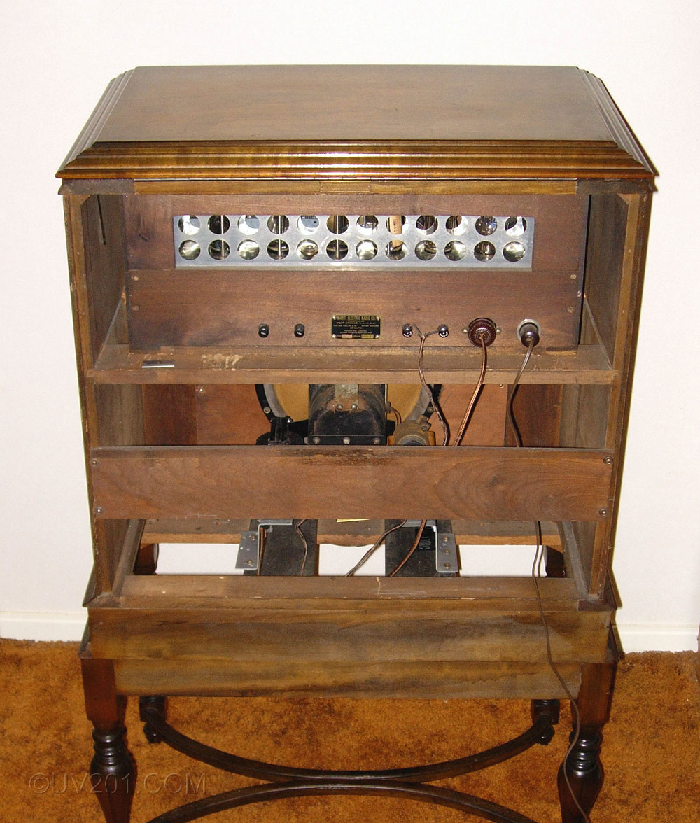
This view shows the Marti chassis enclosed in a wood housing. This unit slid into the cabinet as seen in the rear view, below. A protective wood cover panel (not shown) is normally installed so that the owner could not get his fingers inside the set and risk what would have been a very nasty shock. The toggle switch at the left selected a standard external antenna, or it could use the power line as the antenna. The toggle switch at the right selected an antenna input that was appropriate for a long or short antenna. The power line antenna feature does work, but reception using it tends to be very noisy. A phonograph input jack is provided between the third and fourth tubes from the right. It connects directly to the grid of the detector tube. The phonograph pickup was expected to have an integral volume control. Inside the cabinet, at the far left, is a jack which was provided to allow a speaker field coil to be inserted into the circuit. It is not used in this radio. When the wood cover is installed, only the two toggle switches are accessible. |
 |
 |
|
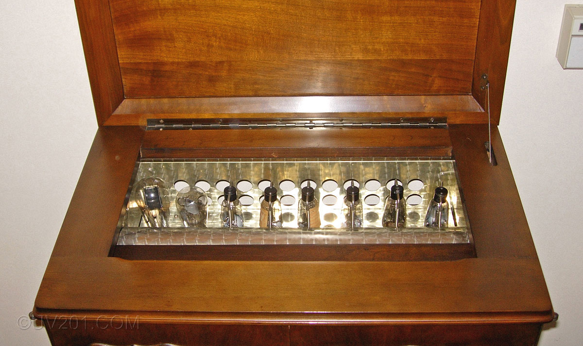
The top of the chassis can be reached by lifting the cabinet lid. The protective wood cover panel is in place at the front of the chassis. |
 |
|
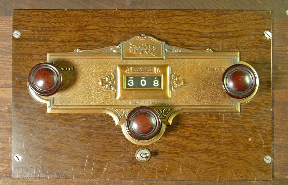
The control panel of the radio is accessed through a cutout in the front of the cabinet. The panel is aluminum, with a wood-grain finish. The tuning control is at the right, the volume control is at the left, and the power switch is at the bottom. In the center is a control marked "sensitivity". This is a small variable capacitor which is in parallel with the first section of the four-gang tuning capacitor. It served to adjust that stage for maximum amplification but I suspect that it was actually added to provide a way to detune the radio as a way to keep it from oscillating, a common problem with these sets. The illustrations of this radio in the original advertisement showed two alternate control layouts. One had two knobs and a toggle switch, and the other had three knobs and no toggle switch. I can't say for sure if the illustrations were simply incorrect, or there were design changes in this area. |
 |
 |
|
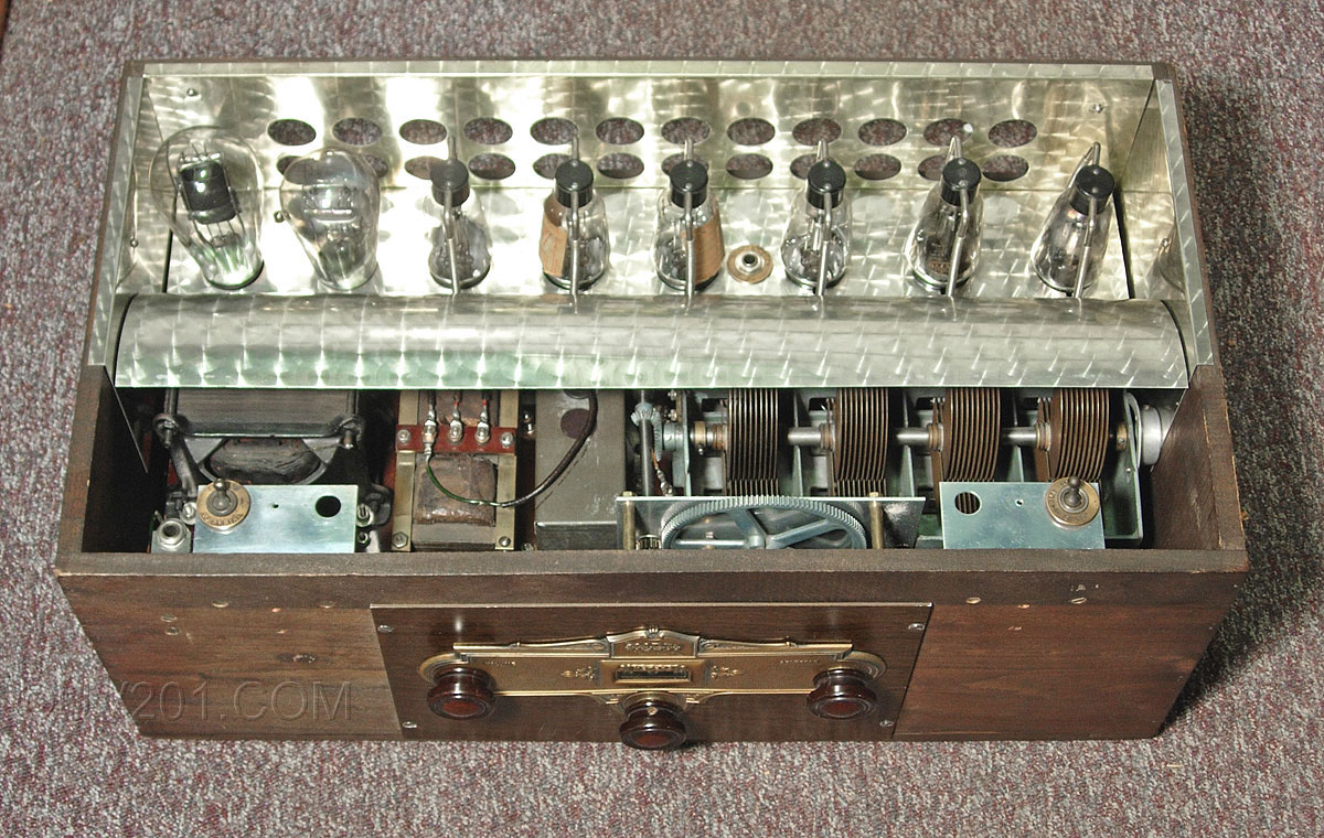
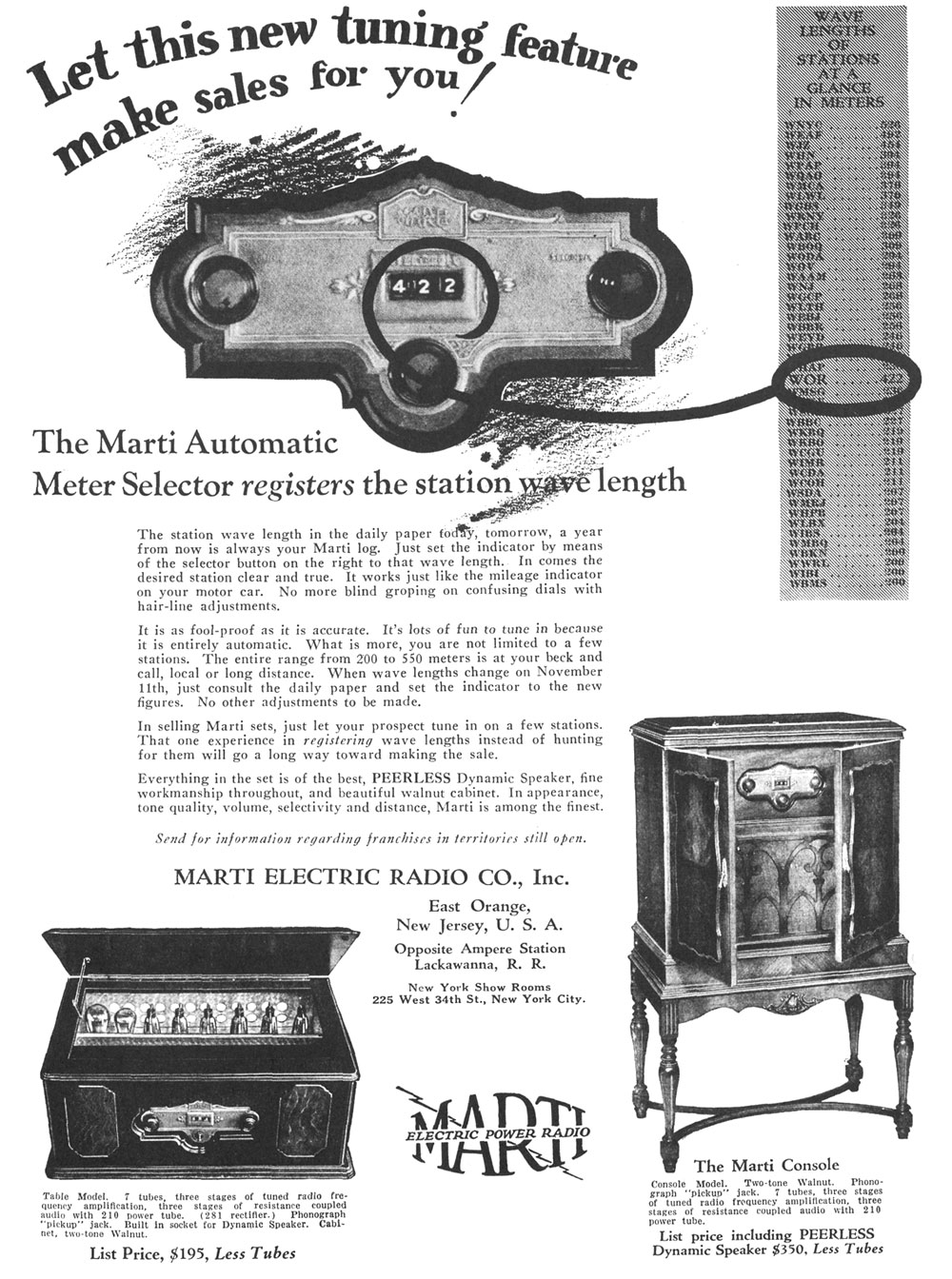
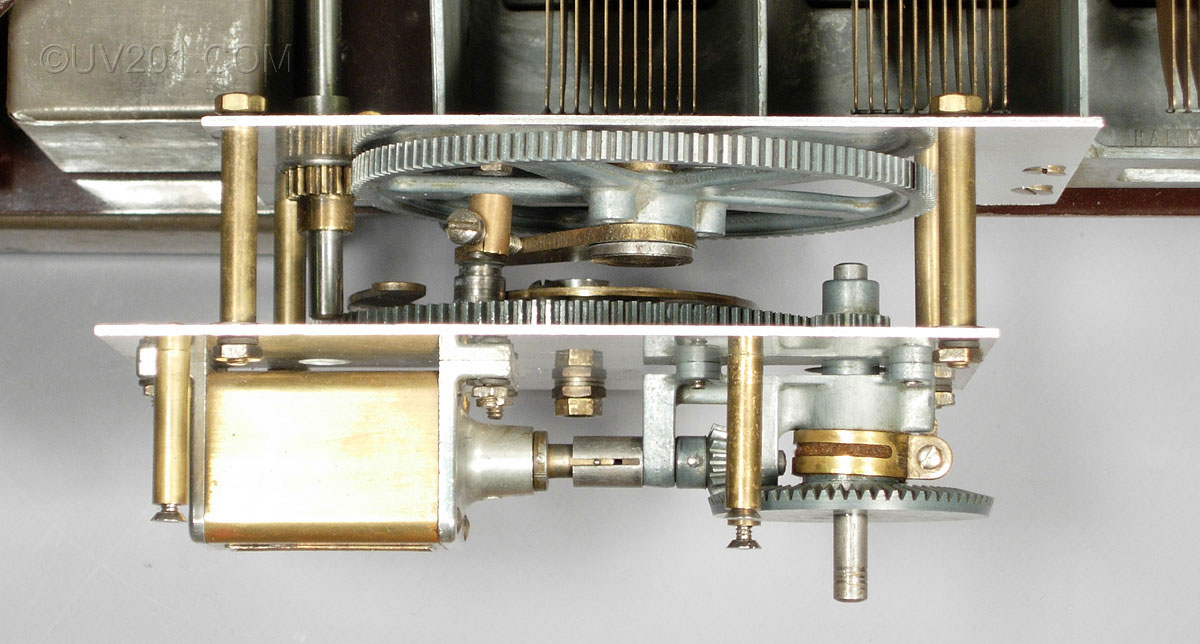
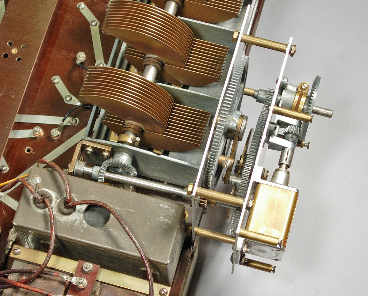
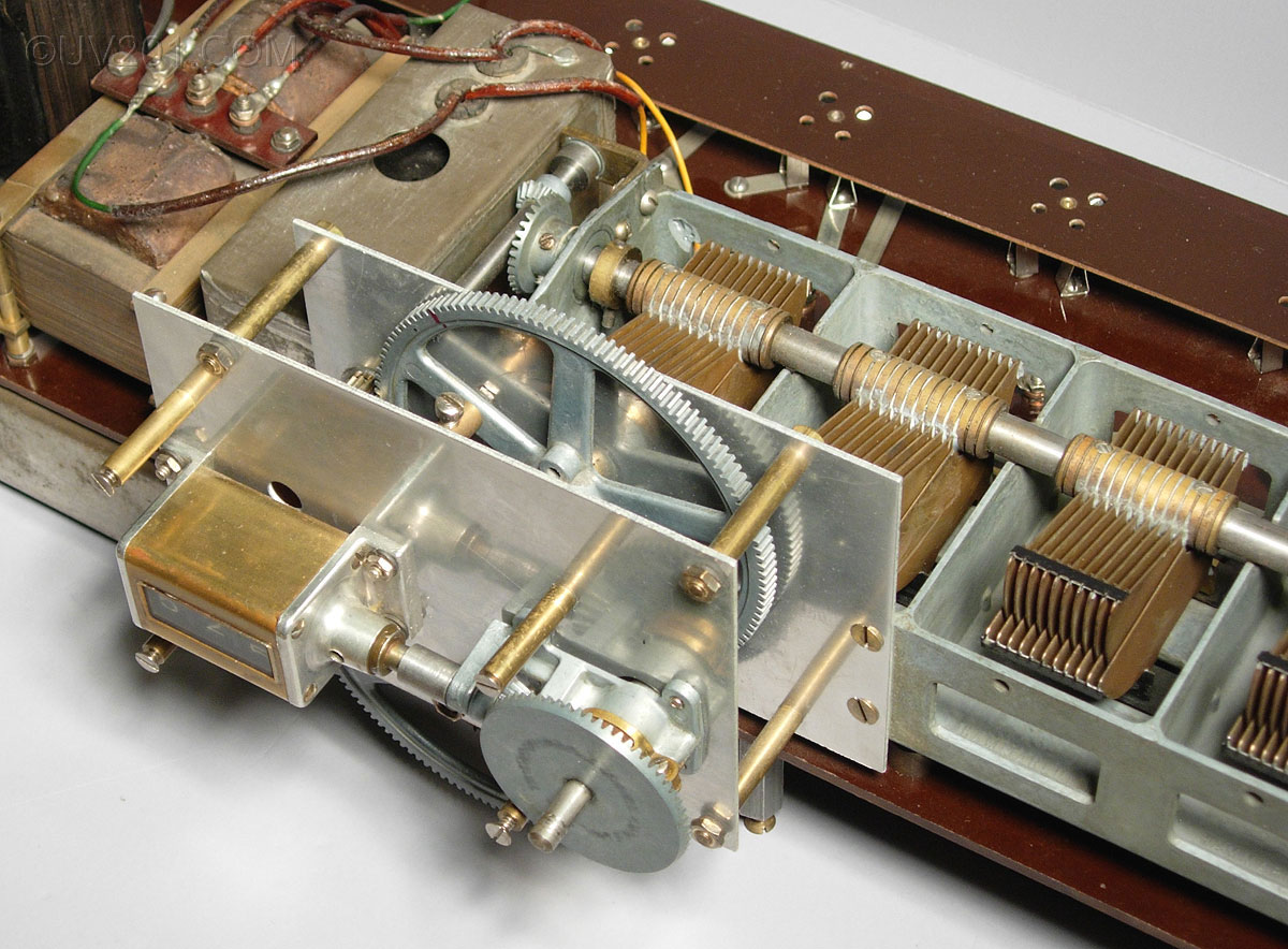
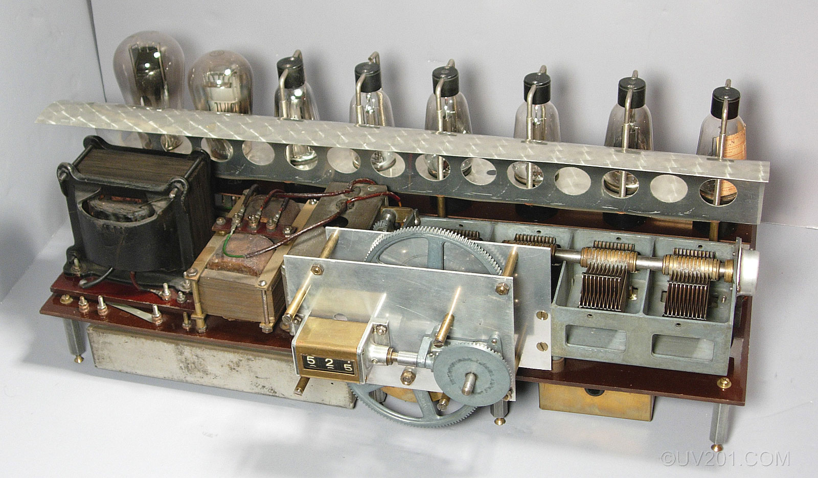
By far, the most unique feature of this radio is the tuning mechanism. This Marti offered a calibrated tuning dial which, by itself, was very unusual for the time. Not only was it calibrated, but it offered a direct digital readout of wavelength. This sort of readout reappeared decades later in high-end communications receivers (such as the Collins R-390/URR), though all later receivers were calibrated in frequency rather than wavelength. I know of no other tube-era home radio that had this feature. The tuning range is 200 meters to 550 meters (550 kHz to 1500 kHz). The tuning knob operates a set of bevel gears which operate a standard 3-digit mechanical turns counter as the readout device (made by Veeder). It also turns a small pinion gear, which drives the first of the two large gears (the one closest to the front of the radio). The second large gear drives another small pinion gear which, in turn, drives the shaft which operates the tuning capacitor through another set of bevel gears. A cam mounted on the first large gear and a cam follower mounted on the second large gear establishes the linkage between the two. A single screw adjustment is provided at this point. A coil spring (similar to a clock spring) located at the far end of the tuning capacitor tries to keep the rotor in its fully open position. The force of the spring holds the cam follower against the cam. The tuning mechanism works against this spring to move the rotor to the desired position. The accuracy of the tuning depended entirely on the profile of the cam. Over the years, the various parts have worn through use, and the die-cast gears have warped slightly, so now it is only possible to have an accurate setting at one wavelength, and there is now some backlash in the gears which means that the accurate setting can only be achieved when tuning in one direction. It takes about 10 turns of the tuning knob to tune this radio through its full range. The action of the counter can be felt as well as heard as it operates. |
 |
 |
 |
|
These pictures show the chassis as it appears once it is removed from its housing. The Kellogg tubes have their filament terminals at the top, and connections are made from below. Each connector consists of a vertical coil spring (to accommodate variations in tube size) and an "L" shaped rod at the top. These rods are drilled out and slotted to be a press fit over the tube's terminal. Though they look exotic, they aren't very reliable and will occasionally pop off. |
 |
 |
|
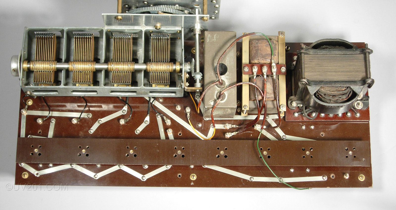
With the decorative panel removed, the top side of the chassis can be seen in detail. At the far left end of the tuning capacitor (which was made by Hammarlund), is a metal cap which encloses the coil spring. The power transformer and two chokes are at the top right, and a can containing three paper capacitors is just right of center. The tube sockets run the length of the Bakelite chassis panel. Unlike earlier Marti's, this design placed the power transformer, chokes, and filter capacitors directly on the chassis. This allowed the set to be operated outside of the cabinet, a boon to the technicians who had to keep these sets operating. The UX-210 tube requires a very high plate voltage to operate properly, in this case, 450 volts. If the output tube burns out, and doesn't load the power supply, this voltage can rise another 100 volts. It is definitely a good idea to keep your fingers out of the wiring, but amazingly, the underside of the chassis is largely exposed when it is installed in the cabinet. The Marti design relied almost exclusively on mechanical connections (nuts, bolts, and lock washers) and metal strips to connect the various components together. There are only a very few soldered connections. This system was one of the weak points of the Marti radio design. The connections had to be kept tight to keep the radio working properly. The heavy power transformer and chokes put considerable stress on the chassis, so care is necessary when handling it. Once installed in its housing, it is well supported, however. |
 |
|
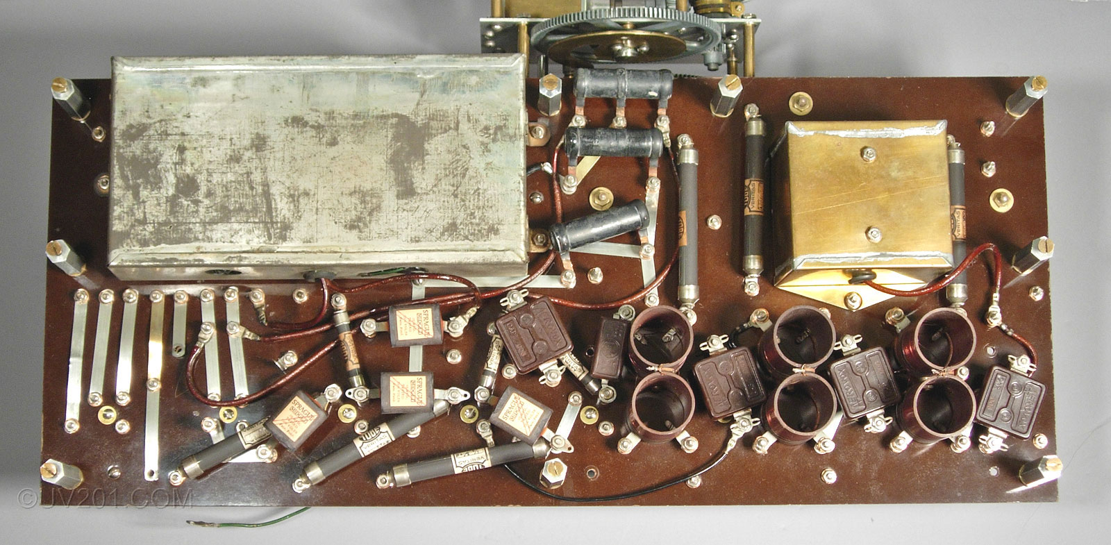
The largest object under the chassis is a can containing the filter capacitors. At the upper right corner is a brass shield enclosing the antenna coil. The three "figure-8" objects are the coupling transformers for the three RF amplifier stages. The remaining parts are resistors and capacitors throughout the circuit. |
 |
|
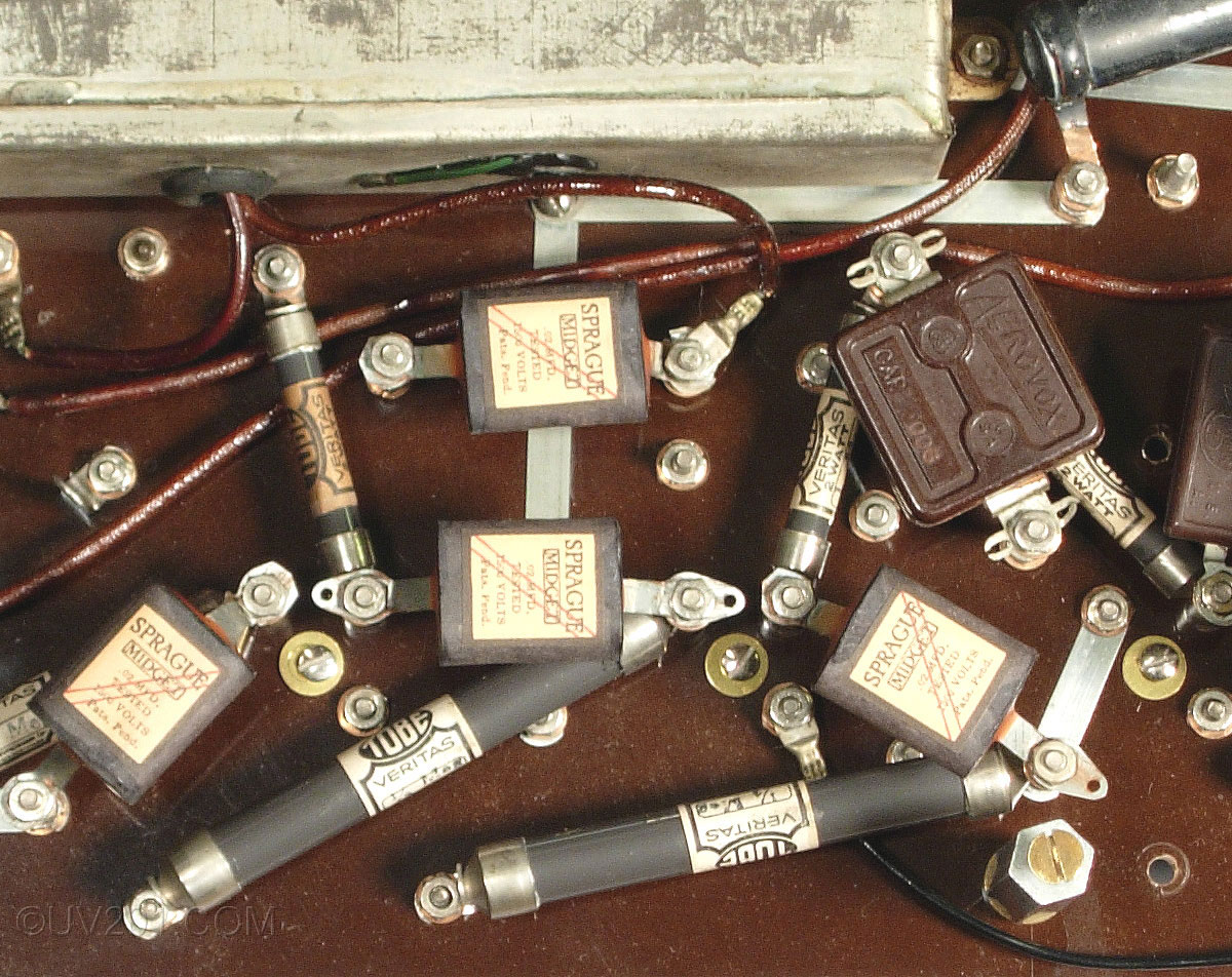
In a closeup view of the underside, you can see some of the components. The four capacitors marked "Sprague Midget" are reproductions of the originals which were, of course, bad. The long cylinders are resistors. Most of them are Tobe Veritas units, which are glass tubes with metal end caps containing resistive material. Except for two that were open, every one of these resistors are still good after 80 years, many reading within 1% of the marked values, which is truly remarkable. Most resistors of this vintage have greatly increased in value and are totally unusable. |
 |
|
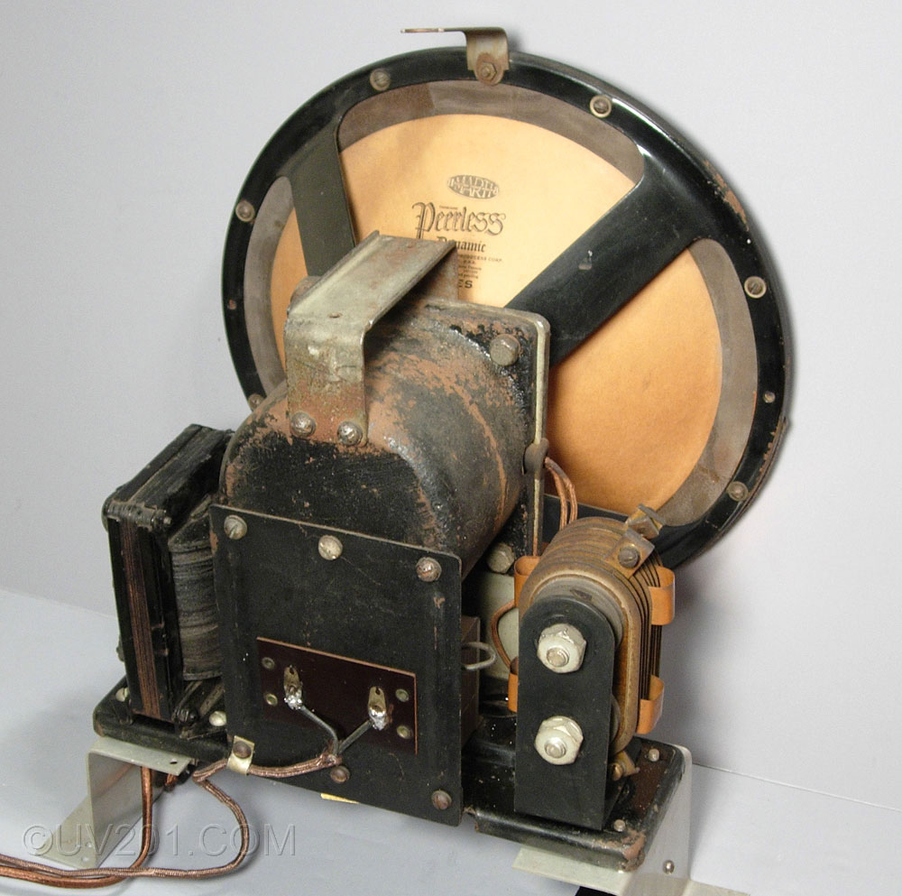
The speaker that was provided with the Marti is the 10 inch Peerless Dynamic Type C. It is a unique design that was widely used in high-end radios in the late twenties. The voice coil is not a coil in the usual sense. Rather, it is a single turn formed from a flat strip of copper sheet. An impedance matching transformer is provided that is mounted directly below the field coil housing, and is not visible in the photograph. The secondary of this transformer is also a single turn made from the same copper sheet. Current for the field coil is provided by a DC supply mounted on the speaker frame base. A transformer is at the left and a full-wave bridge copper oxide rectifier is at the right. This supply provides about 12 volts to the field coil which draws about 2 amps. Except for the voltage, the transformer and rectifier are similar to what would have been used as a battery charger of the day. The original rectifier is no longer functional, so I installed a modern silicon bridge rectifier underneath where it is barely visible. I also added a capacitor to reduce the hum, but there is still a noticeable amount of hum due to inductive coupling between the field supply transformer and the impedance matching transformer. The cone is paper and the surround is suede leather, which is still quite supple after more than 80 years. The speaker sounds quite good for one that old, though there isn't much high frequency response. |
 |
|
This radio has been restored to operating condition. New capacitors have been installed inside the two cans. Several new resistors have been carefully located so that they are nearly impossible to see. The entire chassis assembly was disassembled and cleaned, and the tuning mechanism, which was frozen when I got it, has been restored to near perfect operation. Fortunately, the cast parts in this radio (the tuning capacitor frame and gears) were not subject to the dreaded "pot metal disease" that has caused many of the mechanical parts in early radios and phonographs to swell, warp, crack, and crumble. This was a problem supposedly caused by poor control of the alloy used in these castings. The presence of lead in the mix has been identified as the problem. The cabinet was in excellent condition when I got it. The radio had always been well cared for in a clean, heated house. I replaced the grill cloth with some identical cloth that I was able to salvage from a junk Victor Credenza phonograph. The front view photograph at the top of the page shows a dark circular area where the speaker is located. This was due only to the flash from the camera reflecting off of the light-colored speaker cone (which is why virtually all speaker cones are black). In normal light, the cloth is even in color. A hand-drawn schematic of this radio appears here. The only published technical documentation on Marti radios (Rider's Perpetual Troubleshooter's Manual) appears here. |
|
|